Help
To open this menu again click on on the top right.
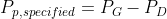
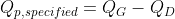
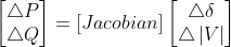
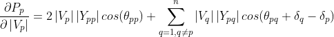
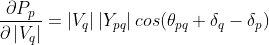
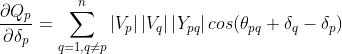
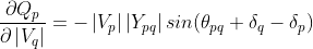
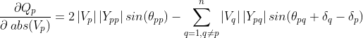
Formulae needed for the execution of power flow analysis using Newton Raphson method


Losses
Power losses in the (i – k)th line = Sik + Ski.
Total transmission losses can be computed by summing all the line flows (i.e., Sik + Ski for all i, k).
It may be noted that the slack bus power can also be determined by summing the power flows on the lines terminating at the slack bus.
Losses
Power losses in the (i – k)th line = Sik + Ski.
Total transmission losses can be computed by summing all the line flows (i.e., Sik + Ski for all i, k).
It may be noted that the slack bus power can also be determined by summing the power flows on the lines terminating at the slack bus.
| Field | Explanation | General Range |
|---|---|---|
| Number of buses | A bus is a junction (or node) where a line or several lines are connected and may also include several components such as loads and generators in a power system network | 1 to 100 (but not restricted) |
| Number of PV buses (including slack bus) | Number of PV buses present in the network. Where, the PV bus is also known as generator bus, voltage-controlled bus, represents the generator stations found in a power system network | 1 to 100 (but not restricted) |
| Number of PQ buses | Number of PQ buses present in the network. Where, the PQ bus is also known as load bus, represents the real and reactive power consumed in a power system network | 1 to 100 (but not restricted) |
| Number of transmission lines | Number of transmission line present in the network. Where, a transmission line used to transmit electric power over relatively long distances, usually from a central generating station to main substations | 1 to 100 (but not restricted) |
| Number of transformers | Number of transformer present in the network. Where, a transformer is an electrical equipment that transfers electric power from one circuit to another circuit without changing the frequency | 1 to 100 (but not restricted) |
| SLACK BUS | ||
| Id of slack bus | Identification number of the slack bus to be entered. Where, slack bus is a reference bus or swing bus | 1 to 100 (but not restricted) |
| Maximum number of iterations | Iteration is the repetition of a process in order to generate an outcome. Each repetition of the process is a single iteration, and the outcome of each iteration is then the starting point of the next iteration | 1 to 100 (but not restricted) |
| Convergence tolerance for voltage difference in per unit | Convergence is the state when all buses have met the mismatch tolerance. In this method the voltage updates one bus at a time until all buses are within the mismatch tolerance | 0.0001 p.u. to 0.001 p.u. |
| Base MVA | Base Mega Volt Ampere | 100 to 600 MVA |
| Acceleration factor | An acceleration factor is a value that can be used to speed up the convergence and reduce the number of required iteration in a Gauss Seidel method of power flow analysis | 1.1 to 2 (Recommended value of the acceleration factor is 1.6) |
| PV BUS | ||
| Id number of the bus | Identification number of the bus | 1 to 100 (but not restricted) |
| Active power generated in MW | It is the three phase Active power generated by the Synchronous Generator and it is measured in megawatts (MW) | 0 W to 1000 MW (but not restricted) |
| Reactive power generated in MVAR | It is the three phase Reactive power generated by the Synchronous Generator and it is measured in megavolt ampere (MVAR) | 0 VAR to 1000 MVAR (but not restricted) |
| Upper limit of reactive power in MVAR | The maximum capacity of reactive power generation by the Synchronous Generator | 0 VAR to 1000 MVAR (but not restricted) |
| Lower limit of reactive power in MVAR | The minimum capacity of reactive power absorption by the Synchronous Generator | -1000 VAR to 0 MVAR (but not restricted) |
| Voltage magnitude in p.u. | The magnitude of the voltage at the bus in per unit | 0.9 p.u. to 1.05 p.u. (but not restricted) |
| Angle of voltage (only for slack bus / bus with the slack Id selected in previous step) | The angle of the voltage at the bus in degrees | -90 degrees to 90 degrees |
| PQ BUS | ||
| Id number of the bus | Identification number of the bus | 1 to 100 (but not restricted) |
| Active power demand | It is the three phase Active power consumed by the load and it is measured in megawatts (MW) | 0 W to 1000 MW (but not restricted) |
| Reactive power demand | It is the three phase Reactive power consumed by the load and it is measured in megavolt ampere (MVAR) | 0 VAR to 1000 MVAR (but not restricted) |
| Flat voltage magnitude in p.u | Flat voltage profile for load bus (in order to perform the power flow analysis, the voltage magnitude is initially assumed as 1 p.u.) | 0 VAR to 1000 MVAR (but not restricted) |
| Angle of voltage | The angle of the voltage at load bus in degree. (in order to perform the power flow analysis, the phase angle of voltage is initially assumed as 0 degree) | 0 degree |
| Id number of the line | The identification number to indicate the transmission line | 1 to 100 (but not restricted) |
| Id number of the sending end bus of the line | The identification number to indicate the sending end bus of the transmission line | 1 to 100 (but not restricted) |
| Id number of the receiving end bus of the line | The identification number to indicate the receiving end bus of the transmission line | 1 to 100 (but not restricted) |
| Resistance of the line in p.u | The resistance of the transmission line in per unit quantities | 0 p.u. to 2 p.u. (but not restricted) |
| Reactance of the line in p.u. | The reactance of the transmission line in per unit quantities | 0.0001 p.u. to 2 p.u. (but not restricted) |
| Half-line charging susceptance in p.u | The half-line charging susceptance of the transmission line in per unit quantities | 0 p.u. to 0.5 p.u. (but not restricted) |
| Id number of the transformer | The identification number to indicate the transformer | 1 to 100 (but not restricted) |
| Id number of the sending end bus of the transformer | The identification number to indicate the sending end bus of the transformer | 1 to 100 (but not restricted) |
| Id number of the receiving end bus of the transformer | The identification number to indicate the receiving end bus of the transformer | 1 to 100 (but not restricted) |
| Resistance of the transformer in p.u | The resistance of the transformer in per unit quantities | 0 p.u. to 2 p.u. (but not restricted) |
| Reactance of the transformer in p.u | The reactance of the transformer in per unit quantities | 0.0001 p.u. to 2 p.u. (but not restricted) |
| Off nominal tap ratio | The off-nominal tap ratio of the transformer in per unit quantities. This ratio determines the additional transformation relative to the nominal transformer | 0.1 to 2 (but not restricted) |