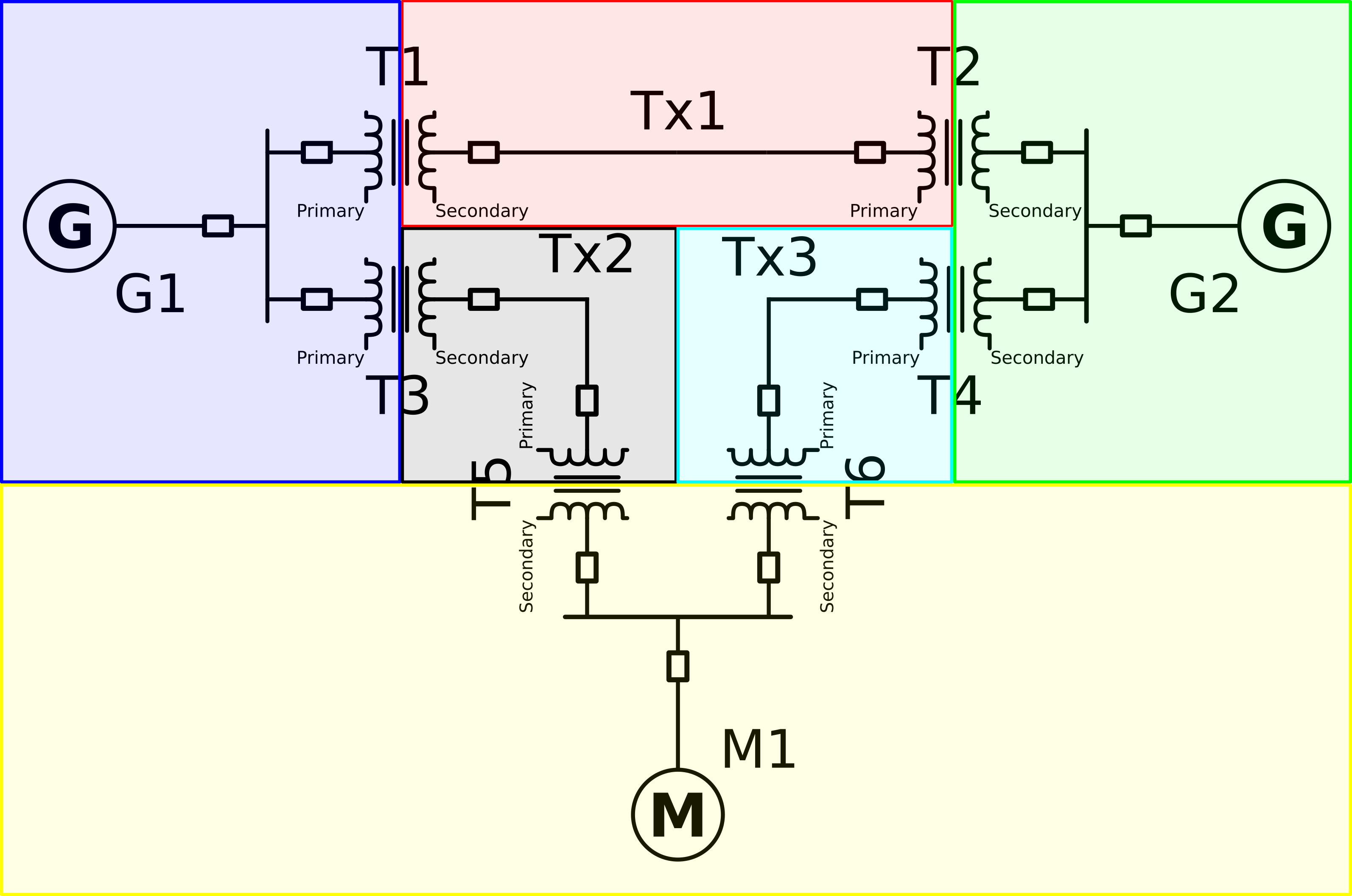
 The Given power system model can be divided into 6 regions namely R1: Blue, R2: Red, R3: Green, R4: Black, R5: Cyan, R6: Yellow
The components in R1 are:
- G1
- Primary of T1
- Primary of T3
- Secondary of T1
- Tx1
- Primary of T2
- Secondary of T2
- Secondary of T4
- G2
- Secondary of T3
- Tx2
- Primary of T5
- Primary of T6
- Tx3
- Primary of T4
- Secondary of T5
- Secondary of T6
- M1
- First choose a component to be the base for the entire system (In this section we explain with Tx1 as the component).
- Since we have chosen Tx1 as our base component we will consider its MVA as the base MVA for the entire power system.
- To determine the base kV though we have to divide the components into regions divided by transformers as shown in the above image.
- Once divided, assign the base kV of R2 as the kV of Tx1 this is because the base kV of the region containg the base element is the base kV of the base element.
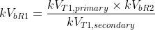
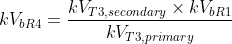
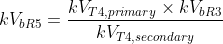
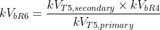
- Now The calculation of the base kV for region 1, 3, 4, 5 and 6 has to be done this is done using the below formule
- Once base kV for all the region have been found the perunit impedance can be found using the following formule (here for new base kV of the component use the calculated base kV of the region the component is in)

 OR
OR
Where kVbRn is the base kV of region n, kVTn,(primary/secondary) the rated kv of the primary/secondary side of transformer n (Tn)


NOTE: The kVb,given, Zpu,given, MVAb,given are the component's kV, Zpu, MVA. The "given" may be replace by "old"
